

Heat Engineer Software Founder and CTO Rich Cartwright delivered a technical presentation in Newcastle on 4 June 2026, exploring some of the key factors that influence domestic heat loss calculations — with a particular focus on ventilation, air permeability and the importance of accurate property data.
The session, hosted by Dominic Eves and Craig Gilhome, brought together practical installation experience with the increasingly detailed requirements surrounding modern heat loss calculations.
The presentation, titled “Understanding Heat Loss, Ventilation and Air Permeability”, was designed as a practical session for heating professionals, covering data collection, calculation methodology and the influence that a building’s airtightness can have on calculated heating demand.
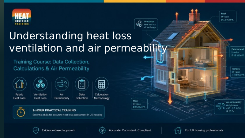
Getting the fundamentals of heat loss right
One of the central themes of the session was that an accurate heat loss calculation is only as reliable as the information used to produce it.
Rich explored the different information needed when assessing a property, including:
- Room and building dimensions
- Building fabric and U-values
- Internal design temperatures
- External design temperatures
- Thermal bridging
- Air permeability
- Minimum room air change requirements
The presentation also looked at how the industry is changing the way this information can be captured.
Traditional laser measurements and existing drawings remain important, but engineers can now also use digital floor-plan creation, LiDAR room scanning and 360-degree camera technology to speed up surveys and create a more detailed record of a property.
The message throughout the session was that technology should make data collection easier without removing the engineering understanding required to interpret that information correctly.
Why ventilation heat loss deserves more attention
A significant part of the Newcastle session concentrated on ventilation heat loss and infiltration.
Fabric heat loss through walls, floors, roofs, windows and doors is generally well understood. However, uncontrolled air leakage can also make a significant contribution to the heating requirement of a property.
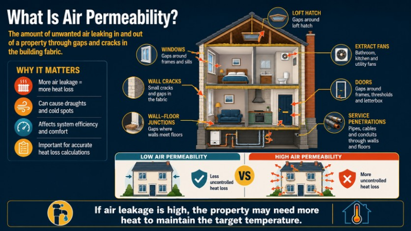
Air permeability describes the amount of unwanted air that can leak into and out of a building through gaps and cracks in its fabric. Typical leakage paths can include windows and doors, wall-to-floor junctions, loft hatches, service penetrations and other imperfections within the building envelope.
The implications are important: a less airtight property can experience greater uncontrolled heat loss, draughts and cold spots, which ultimately affects comfort, system sizing and heating-system performance.
Understanding the latest calculation methodology
Rich also discussed the move towards calculations based on BS EN 12831-1:2017, alongside the approach contained within the CIBSE Domestic Heating Design Guide 2026.
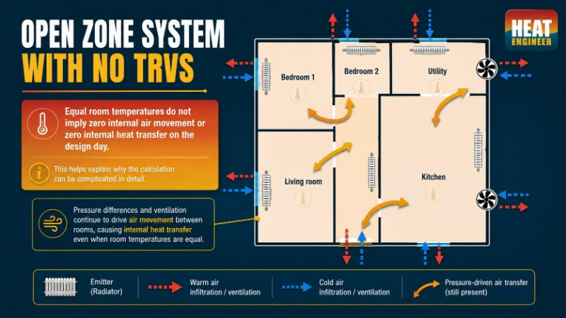
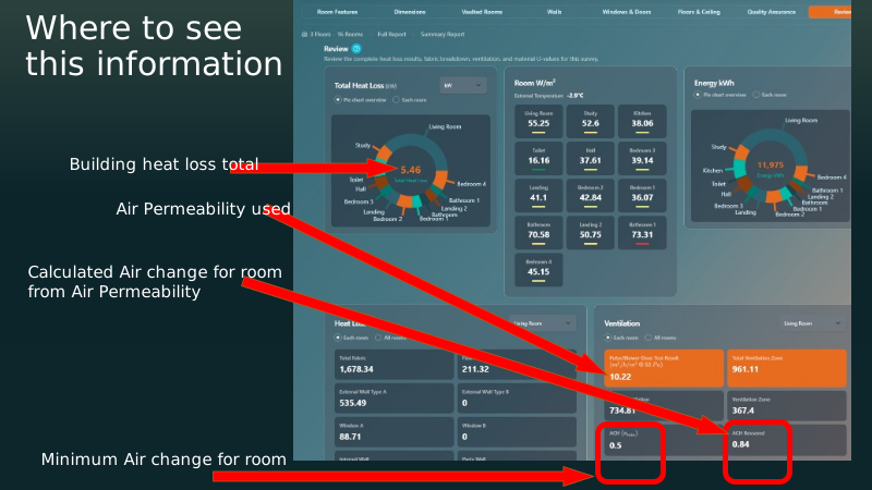
Particular attention was given to the relationship between room level ventilation calculations and the total building or heating zone calculation.
The presentation explained how the methodology considers air permeability, minimum room air-change rates and wind-driven infiltration, including the use of the fi-z factor of 0.5 in the common UK case.
This leads to an important point that can initially appear counterintuitive: adding together the calculated heat losses of every individual room does not necessarily produce the same result as the building or zone heat loss.
Understanding why these figures differ is particularly important when moving from room-by-room emitter sizing to the selection and sizing of the overall heat source.
How much difference can air permeability make?
The session then moved from theory into practical examples.
Rich highlighted 2025 research by Loughborough University for DESNZ, which analysed 12,277 low-pressure Pulse airtightness test results across 8,933 unique addresses. The study reported a mean air permeability of 8.6 m³/h·m² at 50 Pa, suggesting that the GB housing stock may be more airtight than previously thought.
- Low-pressure Pulse airtightness test results
- 12,277
- Unique addresses in the analysis
- 8,933
- Mean air permeability at 50 Pa
- 8.6 m³/h·m²
This raises an important question for heating designers: what happens when a generic assumed air-permeability figure is significantly different from the actual property?
A worked example demonstrated the effect.
For the same property, changing the air-permeability input from a measured value of 9.22 to an assumed value of 12 m³/h·m² at 50 Pa increased the calculated building/zone heat loss from approximately 4.95 kW to 5.17 kW.
That represents an increase of around 0.22 kW, or 4.4%, without changing the dimensions, U-values or design temperatures of the property. The largest individual increase occurred in the living room.
- Air permeability, measured to assumed
- 9.22 → 12
- Calculated building or zone heat loss
- 4.95 → 5.17 kW
- Overall increase in the worked example
- +0.22 kW / 4.4%
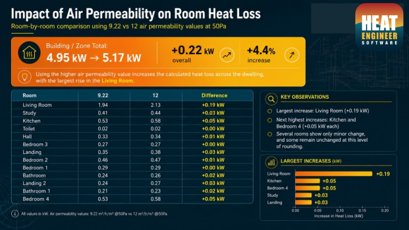
While that difference may appear relatively small in isolation, it demonstrates a wider principle: assumptions made during the survey can flow directly through to heat-source selection, emitter sizing, system flow temperatures and ultimately the efficiency of the finished heating system.
Measured data wherever possible
The presentation therefore encouraged designers to make better use of measured information wherever it is available.
Within the approach demonstrated during the session, a valid Pulse or blower-door test takes priority when establishing air permeability. Where a measured result is unavailable, an as-designed value or an appropriate estimated value can be used, with the designer still responsible for ensuring the selected assumption is appropriate for the building.
This reflects a broader objective within Heat Engineer Software: to give heating professionals greater visibility of the information behind a calculation rather than simply presenting a final heat-loss number.
References and further reading
British Standards Institution (BSI). BS EN 12831-1:2017 – Energy performance of buildings: Method for calculation of the design heat load – Space heating load, Module M3-3.
This is the principal standard discussed in the session and covers calculation of design heat loads for individual rooms, building entities and whole buildings.
CIBSE. Domestic Heating Design Guide 2026, 11th Edition.
The 2026 guide includes a heat-loss assessment method aligned with BS EN 12831-1:2017, updated CIBSE weather data and guidance for low-temperature heating-system design.
CIBSE Domestic Heating Design Guide 2026(opens in a new tab)
MCS. Heat Load Calculator – Technical Documentation.
The MCS calculator calculates building design heat load in accordance with BS EN 12831-1:2017. Its documentation also explains why the whole-building heat load is not necessarily simply the sum of the individual room heat loads.
Roberts, B.M., Li, M., Allinson, D. and Lomas, K.J. (2025). Baseline airtightness of the GB housing stock. Loughborough University for the Department for Energy Security and Net Zero. Research Paper 2025/002.
This is the particularly useful evidence behind the air-permeability section of the presentation. The research reports a mean GB air permeability of 8.6 m³/h·m² at 50 Pa. The authors are members of Loughborough University’s Building Energy Research Group, and the work was undertaken for DESNZ.
CIBSE Domestic Building Services Panel – Heating and Heat Pump Factsheets.
CIBSE recommends a full room-by-room heat-loss assessment incorporating fabric losses, ventilation heat loss and external design conditions rather than relying on whole-house rules of thumb.